
CALL US TODAY
770-591-5271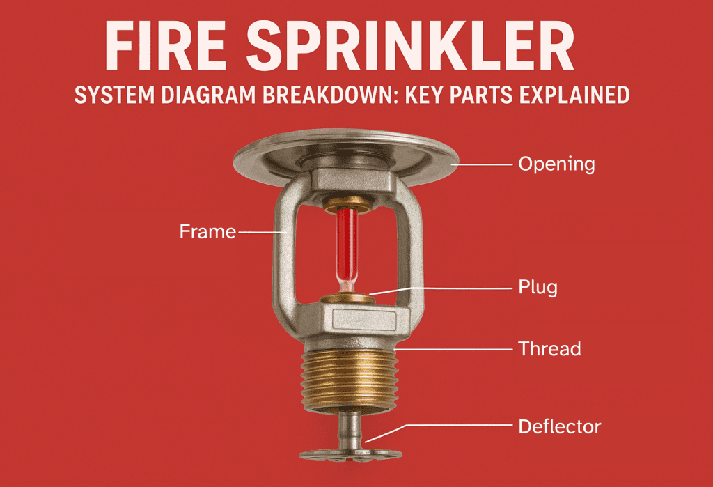
When examining a fire sprinkler system diagram, building owners and facility managers often feel overwhelmed by the complex network of pipes, valves, and components illustrated. Understanding these diagrams is crucial for proper maintenance, compliance, and emergency preparedness. This comprehensive breakdown will help you identify and understand the essential elements that make your fire protection system function effectively.
A basic fire sprinkler system diagram serves as a roadmap for your building's fire protection infrastructure. These technical drawings show the precise placement and connection of every component, from the main water supply to individual sprinkler heads throughout your facility.
The diagram typically displays both the horizontal and vertical pipe runs, indicating water flow direction and pressure points. This visual representation helps fire protection professionals, building inspectors, and facility managers quickly assess system coverage and identify potential issues.
Water Supply and Distribution Network

The foundation of any system begins with the water supply connection. Your diagram will show:
Many systems utilize orange PVC pipe for fire sprinkler systems in certain applications, which may be specifically noted on your diagram with color coding or material specifications.
Critical control components regulate water flow and system operation:
A sprinkler system backflow preventer diagram often appears as a separate detail drawing, showing the specific configuration required by local codes.
The diagram illustrates various sprinkler head configurations:
Pendant sprinkler heads hang down from ceiling-mounted pipes and are the most common type in commercial buildings. These appear as circles or specific symbols indicating their coverage area and activation temperature.
Concealed fire sprinkler heads are shown with special notations indicating their hidden mounting within ceiling tiles or decorative covers. These maintain aesthetic appeal while providing essential fire protection.
Sidewall sprinklers mount on walls and project water in a specific pattern, typically used in corridors or areas where ceiling mounting isn't practical.
Related: How To Clean Fire Sprinkler Heads without Damaging the System
Depending on your building type, additional components may include:
A wet fire sprinkler system diagram shows pipes filled with pressurized water, ready for immediate discharge when a sprinkler head activates. These systems are ideal for heated buildings where freezing isn't a concern.
Dry pipe sprinkler systems, conversely, show pipes filled with pressurized air or nitrogen, with water held back by a special valve. When a sprinkler head opens, the air escapes, allowing water to flow through the pipes.
Fire sprinkler diagrams use standardized symbols and fire sprinkler signs to convey important information:
Understanding these symbols helps you quickly interpret any fire sprinkler system parts diagram and communicate effectively with fire protection professionals.
Your diagram serves as an essential reference during routine fire protection inspections and maintenance. It helps technicians:
Regular review of your system diagram alongside physical inspections helps identify discrepancies that could affect system performance during an emergency.
Building modifications, renovations, or system upgrades require corresponding updates to your fire sprinkler system documentation. Outdated diagrams can lead to confusion during emergencies, complicate maintenance procedures, and potentially result in code violations.
Professional fire protection companies maintain accurate as-built drawings that reflect the current system configuration, ensuring your documentation remains reliable and compliant with local fire codes.
Contact Cliffs Fire Protection today for professional system inspections, diagram updates, and comprehensive fire protection services throughout the Atlanta area. Our BBB A+ Rated technicians provide the expertise you need to keep your building safe and compliant.


 ADDRESS


 Lume Sales & Marketing